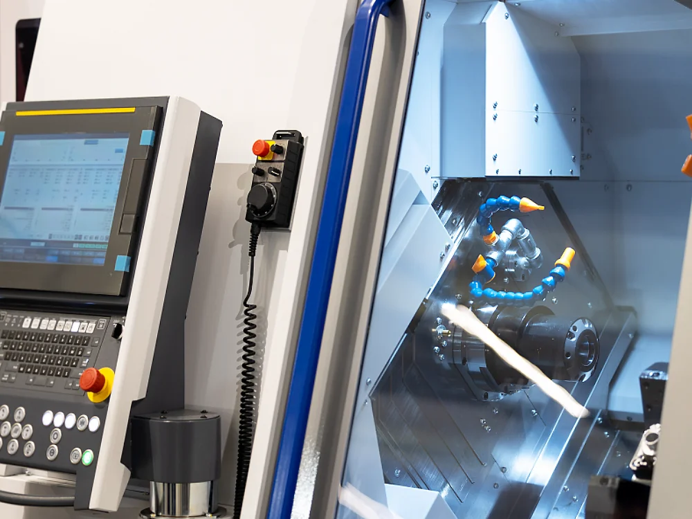
What’s a CNC Control system?
Before discussing the types of CNC control systems, let us first understand what a CNC is;
“The term CNC stands for Computer Numerical Control, which means that a machine is controlled by computer software to make it work automatically, without the need for a human operator. So, software & hardware that controls the whole process is called a CNC control system.” Learn what CNC manufacturing is.
CNC machines are mostly used in industries, but recently, they have become very famous among youth in the form of 3D printers, which are used to make different products from filaments.
It is important to note that the CNC control system minimizes the need for human operators but to how certain extent, it depends on the machine. For example, some require a human helper from time to time while other machines do all the work themself.
Types of CNC Control Systems
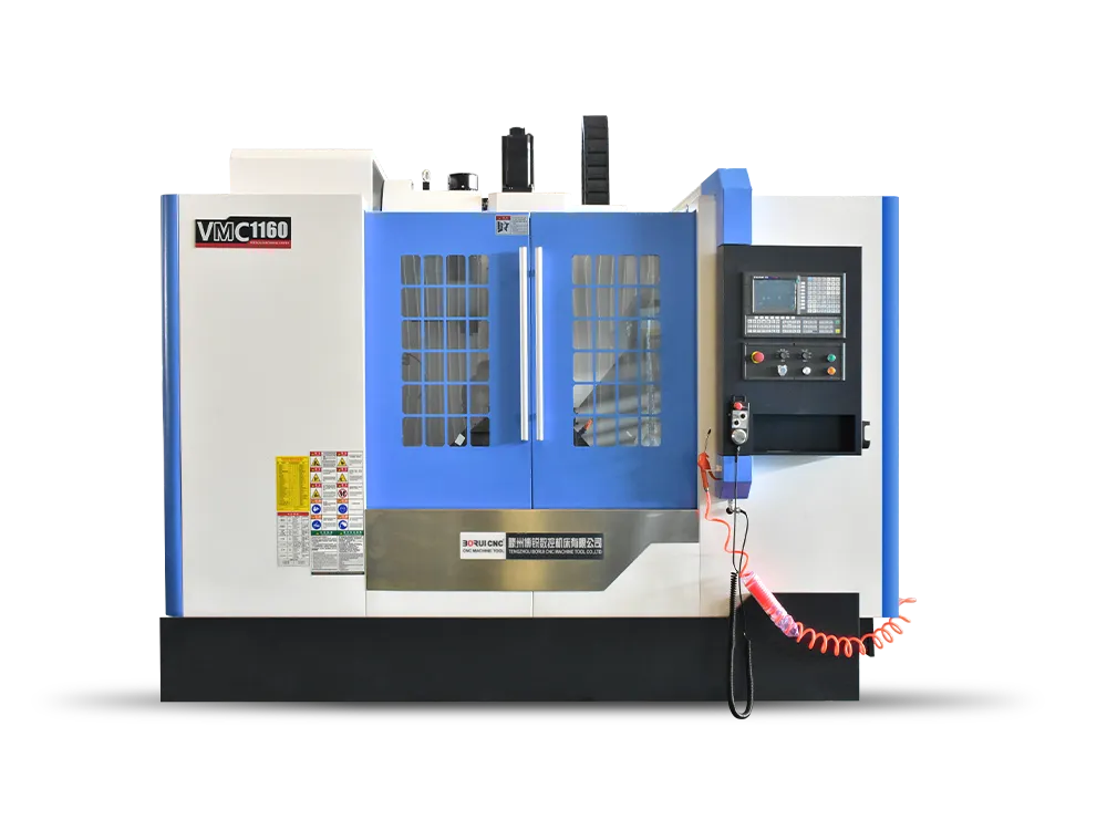
In the world of CNC machines, their structure and function vary. They are used to bend car body sheets, paint products, lift and put stuff, extrude items, tighten bolts, and much more.
So, the CNC control system or software used to control these machines is also very widespread. However, the 3-main parameters that every control system has integrated are discussed below;
- Feedback Loop CNC Control System
- Motion-based CNC Control System
- Number of Axis-based CNC Control Systems
1. Feedback Loop CNC Control System
The first thing that is common sense is that a machine has to be instructed via some instruction ( G-code file ) to work on a specific task or product.
So, when an operator feeds an instruction file to the machine motherboard > it sends the commands to the tools to control their movement and speed. Now, the loop system gets involved;
- Open Loop system: In this type of Control system, the machine’s main motherboard is just given some instructions and then the motherboard sends the signals to the machine parts without knowing the condition of the machine like it’s broken, some parts are missing, etc. There is no feedback mechanism in the Open loop system.
- Closed Loop system: In this control system, after the G-code file is sent to the motherboard, the motherboard gets feedback from the machine and then makes real-time adjustments in the program, so the final work is without any errors. In a closed-loop system, there is an analogue/digital sensor which keeps the watch on the tool’s movement & speed during the operation.
2. Motion-based CNC Control System
So, you have to grasp how the G-Code file/instruction is fed into the machine and how the loop system helps to imply those commands. Now, it is time to learn, which path a tool chooses for a specific operation.
For example, let’s say we want to cut between points A to B, so the question is which path the tool chooses because it also has to be told to the system.
In the CNC Motion-based control system, there are 2 famous tool paths;
- Contouring path: In this control system, small points are specified between the start and finish points so the machine follows a predefined path and gives us the required shape & precision. It is worth noting that we can assign any path, such as a straight line, curve, irregular point, etc., and the control system will make sure that the machine follows that path. A courting path is used for complex operations, such as cutting, welding, routing, and dispensing.
- Point-to-Point: As the name suggests, in the Point-to-Point Control system, in the G-code file, the operator defines the start and end point but the path the tool chooses is decided by the machine ( which is mostly the shortest line between these points ). The Point-to-Point system is used for simple tasks like pick & place and dispensing.
3. Number of Axis-based CNC Control Systems
So, the last thing that the CNC control system has to manage is the movement of the tool head & sometimes the workpiece.
Depending on the number of axes the tool moves, the control system also gets changed. For example,
- 2-axis control system: In this mode, the tool moves along only 2-axis which is X and Y; this means that on a plane surface, the tool moves from point A to B ( X-axis ) and then from B to C ( Y-axis ).
- 2-and-a-half-axis control system: In this mode, the tool moves the X and Y axis the same as in a 2-axis system but it also gets an additional vertical axis Z. It is worth noting that the Z-axis is called the half-axis in this system because it doesn’t move simultaneously along with the X and Y axis.
- 3-axis control system: As the name suggests, in a 3-axis control system, the horizontal X & Y axis and vertical Z-axis have the ability to work simultaneously.
- 4-axis control system: X, Y, and Z-axis, everybody knows them. In a 4-axis control system, one of the axes is given the rotation or angular movement capability.
- 5-axis control system: Similarly, in the 5-axis control system, the program gives the tool the ability to move along the X, Y, and Z-axis with rotations along two of the three axes ( X-axis rotation = C-axis, Y-axis rotation = B-axis, and Z-axis rotation = A-axis ).
It is worth noting the more axis a machine gets, the better it can work on complex operations and make precise products.
But on the downside, the more complex the input program gets and there are more moving parts to take care of. See the difference between 3-axis and 5-axis.
Conclusão
In short, a CNC control system is a combination of software & hardware which manages the data input loop system, and the path the tool takes, and coordinates movement along various axes – it manages all 3 simultaneously.
Further on, the types of control systems indicate how the machine does all that and how complex the control system is based on the work. For example, does it use an open or closed loop, is its toolpath contoured or point-to-point, and what number of axes does a machine have?